Subnets
Subnet Introduction
In the VPC Networking > Subnets view, an IP subnet can be defined in a standard CIDR format, and assigned a name for easy reference throughout the UI. It is used primarily for association with a VPC as described in VPC Introduction. VPC subnets are defined by the following constraints:
The first four IP addresses and the last IP address in each subnet CIDR block are not available for users, and cannot be assigned to an instance.
The second address of the subnet is reserved for the router.
The CIDR block of a subnet may be either identical to the VPC’s CIDR block, which is the case when there is a single subnet, or a subset of the VPC’s CIDR block, when there are multiple subnets. In the latter case, the CIDR blocks of the subnets cannot overlap. The permitted block size ranges from a /28 netmask to a /16 netmask.
Every subnet that is created is automatically associated with the main route table of the VPC. You can change the association. A subnet can be associated with only one route table at a time.
Creating a Subnet
See the video introducing the basics of creating and configuring zCompute VPC Subnets:
To create a subnet:
Navigate to the VPC Networking > Subnets view.
From the top toolbar, click Create.
In the Create Subnet dialog, enter the following:
Name - name of the subnet.
Description - optional description of the subnet.
VPC - VPC which is associated with this subnet.
CIDR - subnet in CIDR format based on IP/mask.
Tags - optionally add tags by selecting them from the dropdown, or creating them in this field.
Subnet Operations
After creating a subnet, it is displayed in the subnet list in the VPC Networking > Subnets view. The following operations can be performed by selecting a subnet from the list, and clicking the appropriate icon.
From top toolbar:
Modify - change the name of the subnet.
- Set Default - set the subnet as the default for a VPC, to be used for
provisioning new entities within the VPC. For example, if a new VM instance is associated with a VPC, it will be configured with an IP from the default subnet.
Delete
Test connectivity - use ping or arping to test connectivity to a specific IP within the selected subnet. For more information on subnet testing, see Testing Subnet Connectivity.
Soft Reset - rebind all DHCP ports on the network.
Hard Reset - recreate DHCP servers on the network.
From lower toolbar:
VMs - view information on VMs associated with the selected subnet.
Events - view configuration events (info) or alarms for the subnet.
In the displayed subnet list, there is an indication of Direct Subnet.
Direct Subnet
In zCompute, a Direct Subnet provides the ability to share the same layer 2 network (VLAN) between the hosting data center’s network and a VPC subnet.
This allows end users who require it, to achieve L2 connectivity over a given VLAN ID to resources external to the zCompute cluster, or direct access to zStorage resources available at the data center.
For example, a direct subnet allows the establishment of external and dedicated VPSA Storage Arrays and Object Storages while bypassing unnecessary internet routers. This is extremely common and useful where a dedicated and high-speed NAS/Object Storage solution is required.
Important
Due to physical network resource allocation, Direct Subnets are managed by the MSP or Zadara Operations team.
Typically, the Direct Subnet’s CIDR is provided by the MSP partner that manages the data center’s routing and IP allocations.
The Direct Subnet’s CIDR and the VPC’s CIDR must be foreign to each other and must not overlap.
DHCP must not be used on this VLAN or subnet, otherwise unexpected DHCP VM configurations might occur.
The VMs’ default GW of VMs attached to the Direct Subnet is always set to the VPC’s internal GW, i.e. the internal vRouter and not the external GW of the Direct Subnet.
The VPC Internal Router IP and all IPs in a Direct Subnet’s Allocation Pool must be managed by zCompute. None of these IPs can be used by external systems on the Direct Subnet VLAN.
See the video introducing the basics of connecting local networks into your VPC with Direct Subnets:
Creating a Direct Subnet
To create a direct subnet (MSP or Zadara Operations team only):
Navigate to Account Networking > Direct Subnets and click + Create.
In the Create Direct Subnet window, enter:
Name: The name of the direct subnet.
Description: Optional description for the direct subnet.
Project: From the dropdown, select the project to which this direct subnet will be associated.
Note
A project can have only one Direct Subnet.
VPC: Optionally, from the dropdown, select the VPC for this direct subnet.
Node Network: Select the network from the dropdown.
VLAN ID: The VLAN ID of the physical switches that the direct subnet will use. This VLAN ID should also be configured on Zadara switches by Zadara Operations, for all the switch ports attached to zCompute nodes as well as the switches’ uplinks to the partner’s upstream switches, and the partner’s switches’ links to Zadara’s switches.
Subnet (CIDR): The direct subnet’s CIDR block. Typically, this CIDR is provided by the partner, to make it routable from the partner’s data center.
VPC Internal Router IP: The first IP address of the CIDR block. The subnet’s virtual router is created by zCompute, and used by payloads created within zCompute to route traffic from the subnet.
Note
This is not an external gateway, but a virtual router created by zCompute.
The Direct Subnet cannot overlap the VPC network prefix.
Similar to other subnets, two IPs are consumed by internal services, so nothing smaller than a /29 can be used.
External Router IP: Optional IP address for the VPC’s external router.
Allocation Pools:
One or more ranges of IP addresses allocated for zCompute payloads of this subnet.
Enter the start and end IP addresses of the range of addresses comprising the pool of addresses, from which subnets can be allocated.
To configure an additional pool of IP addresses, click Add and enter the pool’s start and end IP addresses.
Note
IPs in the allocation pool are managed by zCompute and should not be used by anything on the customer’s side of the network.
The purpose of this configuration is to avoid any potential IP collisions with other IP addresses external to zCompute that might be in use on this subnet, for example, physical L3 switch gateway, physical firewall appliance gateway, and physical servers.
The Internal Router IP address, and the first and last IP addresses of the CIDR block are not permitted in the allocation pool.
Click Finish.
The subnet is immediately available on the specified VPC.
Note
The direct subnet is not displayed in the Account Networking > VLANs Management screen.
However, the direct subnet’s network_id can be viewed using the symp
vlan-pool vlan get <id> command. For example:
vlan-pool vlan get 1a8cd9e6-0d7d-4ada-ac5b-0bad3fdd291e

+-----------------------+--------------------------------------+
| id                    | 1a8cd9e6-0d7d-4ada-ac5b-0bad3fdd291e |
| name                  | none                                 |
| account_vlan_pool_id  | 93cb6144-7f28-44c3-9492-0b46d13da88d |
| created_at            | 2024-11-18T11:47:50Z                 |
| guest_network_pool_id | 684703f5-d641-4ddb-be82-62b81a024509 |
| network_id            | cecc1054-538a-467e-a615-83e750ce04b4 |
| project_vlan_pool_id  | adb0d5ba-7927-4813-aea7-d0f0d568d808 |
| updated_at            | 2024-11-18T11:47:51Z                 |
| vlan_tag_id           | 40                                   |
+-----------------------+--------------------------------------+
Control over VPC Subnet MTU
Users can view and change MTU values per virtual network.
Note
It is not possible to create a direct subnet in the GUI with desired the MTU. However, the MTU can be updated post-creation.
- The relevant networks are:
Edge networks (for MSP administrators only)
Direct networks (subnets)
VPC subnets
The minimum allowed MTU value is 1450 for standard VPC subnets or 1500 for direct subnets or edge networks.
The maximum allowed MTU value depends on the global MTU configured in the cluster (e.g. 9000 or 1500). If the global MTU configured in the cluster is 9000, the maximum allowed MTU value for all virtual networks will be limited to 8950.
If a VM experiences MTU-related connectivity issues and it resides on a public network (connected via a route-table to an internet-gateway), then it is recommended to set that network MTU to no more than 1500.
Modify Edge Network MTU
Navigate to Region Networking > Edge Networks
In the Edge Networks list, select the Edge Network to modify.
In the selected Edge Network’s detail view, on the top menu click Edit.
In the Modify Edge Network dialog, update the MTU value.
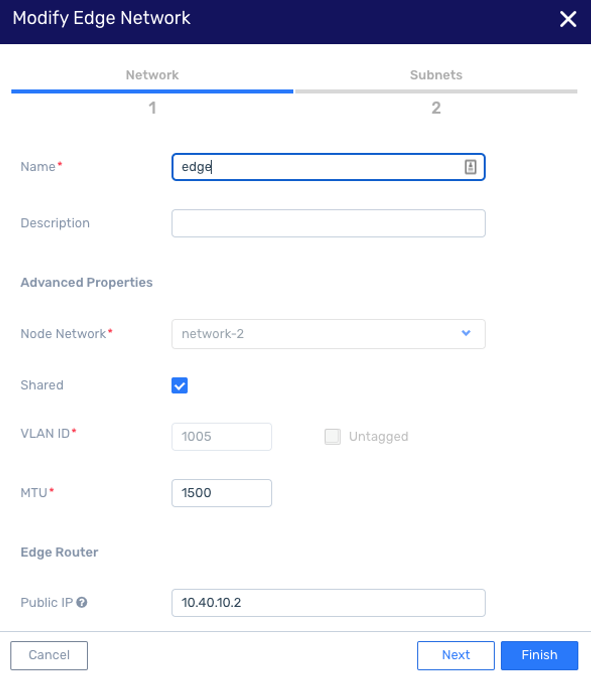
Click Finish to save the updated MTU value.
Modify Direct Subnet MTU
Navigate to Account Networking > Direct Subnets
In the Direct Subnets list, select the Direct Subnet to modify.
In the selected Direct Subnet’s detail view, on the top menu click Edit.
In the Modify Direct Subnet dialog, update the MTU value.
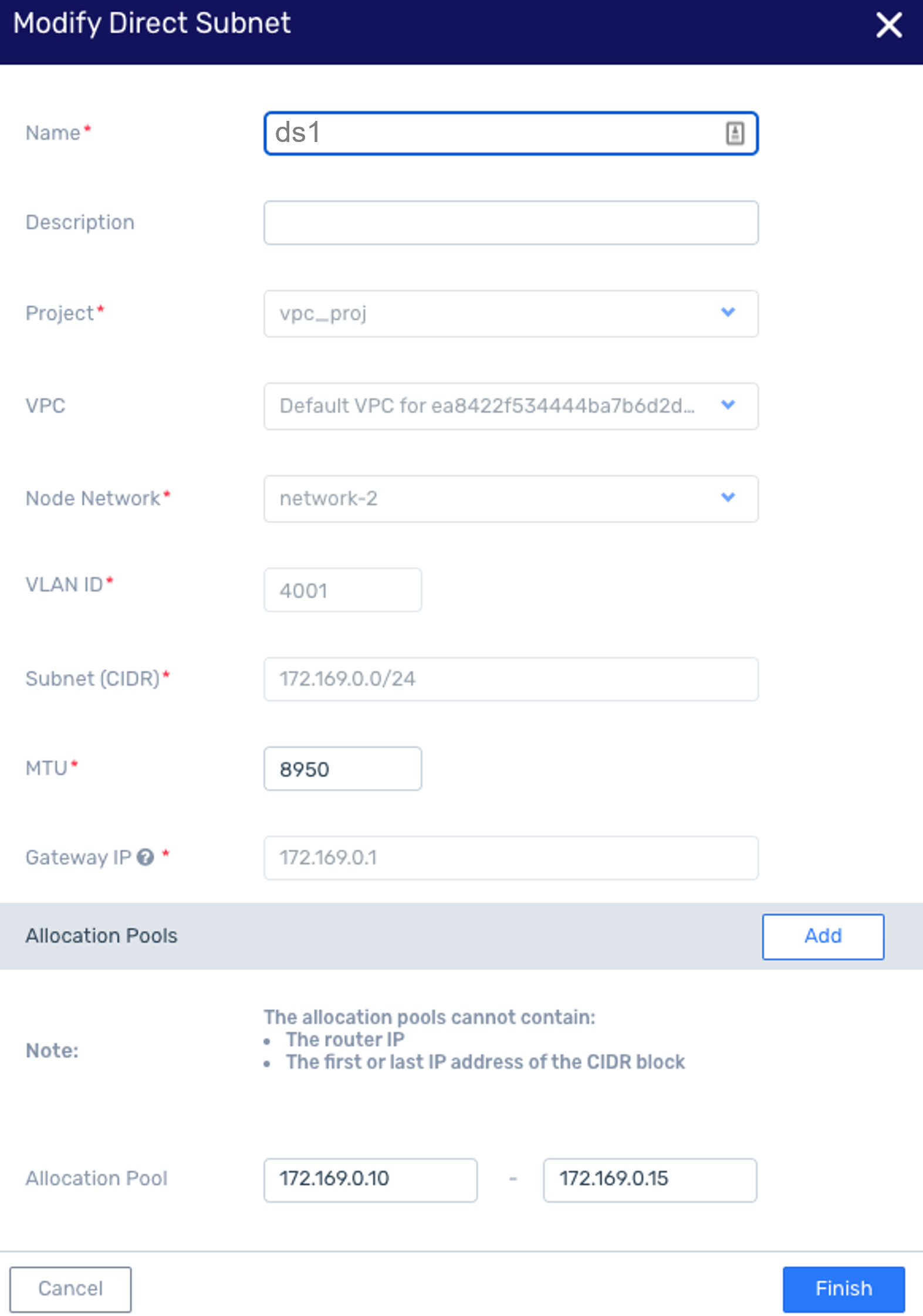
Click Finish to save the updated MTU value.
Modify VPC Subnet MTU
Navigate to VPC Networking > Subnets
In the Subnets list, select the Subnet to modify.
In the selected Subnet’s detail view, on the top menu click Modify.
In the Modify Subnet dialog, update the MTU value.
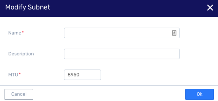
Click Ok to save the updated MTU value.
Note
Routing traffic through an external router
If you want to route traffic from the VPC through an external router connected to the Direct Subnet, the VPC route table associated with the Direct Subnet should be modified.
This can be configured with end user’s tenant permissions.
If an External Router IP was defined in Creating a Direct Subnet, skip to the next step to update the Route Table.
Otherwise, create an Elastic Network Interface:
Navigate to VPC Networking > Network Interfaces and click + Create.
In the Create Elastic Network Interface dialog, enter:
Name: The interface name.
Description: Optional description text.
VPC: The VPC for which the external router is being added.
Subnet: From the dropdown, select the Direct Subnet.
Private IP: The external router’s IP address.
Security Groups: From the dropdown, select the security groups to apply to the network interface.
Click Finish.
Navigate to VPC Networking > Route Tables and click the name of the Route Table to update.
In the selected Route Table’s lower pane, click + Create.
Destination CIDR: The destination network or networks.
Target Type: Select Network Interface from the dropdown, to display the Network Interface input prompt.
Network Interface: From the dropdown, select the network interface created in the previous step.
Click OK.
Testing Subnet Connectivity
Connectivity between a VPC Subnet and a specific IP address can be tested by ping, using either the GUI or CLI.
Using the GUI
Navigate to the VPC Networking > Subnets view.
Select a subnet from the displayed list and click Test Connectivity in top toolbar.
In the Test Connectivity window, enter a Destination IP address.
Select ping or arping.
Note
ping checks layer 3 connectivity, and is blocked by Security Group filtering if traffic is not allowed from any IP in the Subnet.
arping checks layer 2 connectivity, and bypasses Security Group filtering.
Click OK.
Click OK. A message is displayed that the connectivity test is taking place.
A few seconds later, the test results will be displayed indicting success or failure as well as other relevant details. This status report is also available in the right-hand sidebar.
Using the CLI
The ‘guestnet-admin-tool ping-ip create’ command with which you can test a subnet’s connectivity requires the ID of the given subnet (see ‘entity_id’ below). Note: ‘–command-type’ is either ‘ping’ (default) or ‘arping’
guestnet-admin-tool ping-ip create [-h]
                                   [-f {adaptive_table,json,shell,table,value,yaml}]
                                   [-c COLUMN] [--max-width <integer>]
                                   [--noindent] [--prefix PREFIX]
                                   [-m [NAME=VALUE [NAME=VALUE ...]]]
                                   [--command-type COMMAND_TYPE]
                                   [--name NAME]
                                   entity_id dest_ip
Run the ‘vpc network list’ command to locate the ID of Subnet-1.
vpc network list -c id -c nameThis returns a list of subnets and their IDs.
+--------------------------------------+-----------------------------------------------------+
| id                                   | name                                                |
+======================================+=====================================================+
| ceff2b60-fb75-44d0-8b1a-ac4034b260dc | Subnet-1                                            |
+--------------------------------------+-----------------------------------------------------+
Test the connectivity of Subnet-1 to the destination IP address 8.8.8.8.
guestnet-admin-tool ping-ip create ceff2b60-fb75-44d0-8b1a-ac4034b260dc 8.8.8.8This returns a temporary, pending status of the subnet’s connectivity.
+--------------+--------------------------------------+
| id           | 2ce18cc5-b1a8-401c-ae98-99e484f99b3e |
| name         | none                                 |
| status       | pending                              |
| command_type | ping                                 |
| created_at   | 2019-05-12T13:39:56.650560           |
| dest_ip      | 8.8.8.8                              |
| entity_id    | ceff2b60-fb75-44d0-8b1a-ac4034b260dc |
| output       | -                                    |
| project_id   | 07650a05e9dd47c8a3b874a2132e178c     |
| updated_at   | 2019-05-12T13:39:56.650581           |
| user_id      | admin                                |
+--------------+--------------------------------------+
Wait a few seconds and then request the final status of Router-1’s connectivity test by using the ‘guestnet-admin-tool ping-ip get ping_ip_id’, as follows:
guestnet-admin-tool ping-ip get 2ce18cc5-b1a8-401c-ae98-99e484f99b3eThis returns the final, succeeded/failed status of Router-1’s connectivity test with relevant output details.
+--------------+----------------------------------------------------------------+
| id           | 2ce18cc5-b1a8-401c-ae98-99e484f99b3e                           |
| name         | none                                                           |
| status       | succeeded                                                      |
| command_type | ping                                                           |
| created_at   | 2019-05-12T13:39:56                                            |
| dest_ip      | 8.8.8.8                                                        |
| entity_id    | ceff2b60-fb75-44d0-8b1a-ac4034b260dc                           |
|              +----------------------------------------------------------------+
| output       | PING 8.8.8.8 (8.8.8.8) 56(84) bytes of data.                   |
|              | 64 bytes from 8.8.8.8: icmp_seq=1 ttl=118 time=55.1 ms         |
|              | 64 bytes from 8.8.8.8: icmp_seq=2 ttl=118 time=53.3 ms         |
|              |                                                                |
|              | --- 8.8.8.8 ping statistics ---                                |
|              | 2 packets transmitted, 2 received, 0% packet loss, time 1001ms |
|              | rtt min/avg/max/mdev = 53.335/54.219/55.104/0.914 ms           |
|              |                                                                |
|              +----------------------------------------------------------------+
| project_id   | 07650a05e9dd47c8a3b874a2132e178c                               |
| updated_at   | 2019-05-12T13:39:59                                            |
| user_id      | admin                                                          |
+--------------+----------------------------------------------------------------+
Note
This information is automatically deleted after approximately one hour.
Additional options for Subnet (VPC) Connectivity Testing
Delete a specific subnet connectivity test
guestnet-admin-tool ping-ip delete ping_ip_idList all ping_ip requests
guestnet-admin-tool ping-ip list